What this tool does
This site turns a laptop or an Android phone into a Modbus-RTU master so a worker can test an NHOP50x160 hall operating panel without a PLC. Plug a USB → RS485 converter into the computer, wire it to the HOP, and the browser speaks the same protocol the PLC would.
Everything the PLC does with F145 SEND and F146 RECV is available here as
buttons and forms: read the current configuration, change the slave ID and baud rate, drive the display
icon, set brightness, toggle childlock and watch the call button.
Hardware & wiring
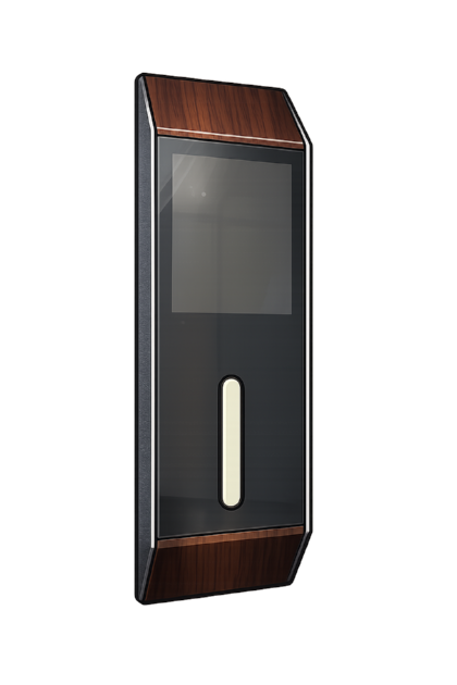
You need:
- A USB → RS485 converter (CH340, CP2102, FT232 and PL2303 chipsets are all supported).
- A 24 V DC supply for the HOP.
- Two signal wires: A and B.
HOP terminal      goes to
-------------     ---------------------------
24V               PSU  +24 V
GND               PSU  0 V  (and adapter GND if it has one)
A                 RS485 adapter  A / D+ / TX+
B RS485 adapter B / D- / TX-The DIP switch on the back of the HOP has two jobs. One position selects SET or RUN mode; another selects Touch Sensing or Touchless for the button. The HOP reads the switch at power-up, so always power-cycle after changing it.
Which browser and which device
| Device | Browser | Works? | Which mode |
|---|---|---|---|
| Windows / macOS / Linux PC | Chrome, Edge | Yes | Web Serial |
| PC | Firefox, Safari | No | Neither API exists |
| Android phone / tablet | Chrome | Yes | WebUSB — needs a USB-C OTG adapter |
| Android | Firefox, Samsung Internet | No | — |
| iPhone / iPad | any | No | iOS blocks serial and USB in every browser |
The page must be opened over https://. Browsers refuse serial and USB access on plain http.
Signing in
- Type your work email on the front page and press Send me a code.
- A 6-digit code arrives by email. It is valid for 10 minutes and works once.
- Type the code and you are in. The session lasts 12 hours on that browser.
Only addresses an administrator has approved can request a code — see User management. There are five attempts per code; after that the code is dead and you must ask for a new one. You can ask for a new code every 45 seconds.
Connecting the adapter
- Pick the connection method (Web Serial on a PC, WebUSB on Android).
- Press Connect adapter. The browser shows its device picker — this dialog comes from the browser, not from this page, and it only appears after a click.
- Pick your converter. The port opens at 115200 8-N-1 on slave 16, which is what the HOP uses in SET mode.
The status strip then shows the port, baud rate, frame format, slave ID, detected device mode, poll interval and the TX/RX/error counters. Change adapter forgets the current device so you can pick a different one.
Under Advanced timing & probe settings you can adjust the reply timeout, the t3.5 frame gap, the retry count and how often the tester polls. Scan bus for the HOP… sweeps a range of slave IDs across the baud rates you tick — use it when you inherited a unit and nobody remembers its settings.
How mode detection works
SET mode and RUN mode both expose a register at H0, so reading one address proves nothing.
The tester therefore reads a whole block and checks every register against the ranges that mode allows.
A mode is only accepted when all of its checks pass.
SET signature — read H0–H9
- H0 slave ID between 1 and 247
- H1 baud code 0–6, H2 data bit 0–1, H3 stop bit 0–1, H4 parity 0–2
- H5 and H6 between 2000 and 10000 ms — the childlock hold times
- H7, H8, H9 no larger than 60000 ms
RUN signature — read H0–H6
- H4 button mode is exactly 1 or 2 — nothing else is legal
- H0, H3, H5, H6 are 0/1 flags
- H2 brightness between 0 and 100
- H1 icon 0–127, or 8501–8599 for a QR code
The two signatures cannot both pass. A device in SET mode holds thousands of milliseconds in H5 and H6, which fails the RUN test; a device in RUN mode holds 0 or 1 there, which fails the SET test. The detect page lists every individual check with the value that was actually read, so you can see exactly why a device was accepted or rejected.
Detection keeps running while you work — by default a fresh read every 700 ms. Flip the DIP switch, power-cycle the HOP, and within a few seconds the tester notices the registers no longer match, goes back to searching, and opens the other mode page on its own. If nothing answers at all the page says Not connected rather than guessing.
Panels & layout
Every section is a panel with two controls in its top-right corner:
- Collapse / expand — the chevron, or click anywhere on the panel header. The state is remembered in this browser.
- Maximise — the arrows. The panel fills the browser window (this is not OS full-screen, so the tabs and address bar stay visible). Press it again, press Esc, or click the dimmed background to restore.
The theme button in the header switches between the dark and light palette.
On a phone
The layout rearranges itself below roughly 700 px wide, so nothing has to be pinched or scrolled sideways:
- The mode buttons (Detect / SET / RUN) move to their own full-width row.
- The status tiles pack three across; the port name keeps a full row to itself.
- The register tables become cards — one card per register, with the value, an input box and the Read / Write buttons stacked. Nothing hides off the right-hand edge.
- Forms go to a single column and buttons grow to a thumb-friendly size.
- Long frames in the traffic log wrap under their timestamp instead of scrolling sideways.
- On this help page the index is behind the Contents button so the text starts straight away.
Maximising a panel on a phone fills the whole browser view, which is the easiest way to work with the icon board or the register table one-handed.
SET mode
The SET page shows what is currently stored in the HOP and lets you change it. Fields with a fixed set of values are dropdowns; timings are dropdowns of the common values with a Custom… entry for anything else. Any field you change is outlined in amber and the counter at the bottom tracks unsaved edits.
- Read from HOP — re-reads H0–H9 and throws away your edits.
- Write all changes — shows a summary of every change first, writes them, then reads back and warns you if anything did not stick.
- Revert edits — restores the form to what the device holds.
- Load document defaults — fills the form with the values from the design document. Nothing is written until you press Write.
RUN mode
The RUN page has two tabs. Live control is the same style of form as SET mode, covering H0–H6, plus the manual register table. Live polling keeps the values refreshing; switch it off if you want the bus quiet while you work with the PLC.
H4 Button Mode is read-only — it reports 1 for Touch Sensing and 2 for Touchless, and is
changed with the DIP switch on the back of the HOP, never over Modbus.
Icons & button tab
The left side is a mock-up of the HOP face. It mirrors what the device reports: the icon currently in
H1, dimmed to match the brightness in H2, flashing when H5 is 1,
and the call button lit when H0 is 1 or amber when childlock is on.
- Tap the round button to toggle
H0between 0 and 1, or use the explicit Send press / Send release / Read button now buttons. - Childlock ON / OFF writes
H3; the blink button togglesH5. - The brightness slider writes
H2when you let go. - The QR box sends 85 followed by your two-digit value — see QR codes.
Below that is the icon board: 128 buttons, one per display code. Click one and it is written straight to
H1 with function 06, so the HOP display changes immediately. Search by name or code, or tick
Named only to hide the codes that have no documented meaning.
Register table
Under each form is a table with one row per holding register: the H address, the 4xxxx equivalent, the
name, the current value and an editable field. Read re-reads that single register, Write
sends just that one with function 06. Read all and Write edited rows work on the whole
table. Values can be shown as decimal, hex or binary, and you may type 0x hex into the input.
Traffic log
Every frame on the bus is listed with a timestamp, direction, the raw bytes and a decoded description.
TX is what the browser sent, RX what the HOP answered, ERR a timeout or bad CRC and
SYS a note from the tester itself. You can pause, filter, copy, or download the whole log as a
.log file to attach to a report. Hide polling frames keeps the automatic reads out of
the log so only the things you deliberately did are shown.
Monitoring graph
Every polled value is plotted against time. Registers are drawn as steps because they are discrete values, not analogue signals. Tick registers on and off in the legend, change the time window, pause the trace, or export everything collected so far as CSV.
SET registers H0–H9
| Addr | 4xxxx | Name | Range | Meaning |
|---|
Baud codes:
RUN registers H0–H6
| Addr | 4xxxx | Name | Range | Meaning |
|---|
H6 Childlock Mode is the
master switch that decides whether the feature exists at all; H3 Childlock State is whether
it is currently locked. Childlock only works in Touch Sensing mode.
Icon codes 0–127
Write the code to H1. Code 0 clears the screen. An invalid code shows black. Names come
from the design document; codes without a name are still valid images on the display.
QR codes (85xx)
Icon code 85 is the QR prefix. To draw a QR code, send 85 followed by a two-digit value as a
single number — the PLC would move K8512 into a DT and send that. So:
8501  ->  QR code holding 01
8512  ->  QR code holding 12
8599  ->  QR code holding 99
Sending plain 85 on its own is not valid; the tester will stop you and explain why.
FPWIN GR7 ladder equivalents
For reference, this is what the same operations look like in the PLC. In H1610 the high byte
is the command (16 = write, 13 = read) and the low byte is the slave ID in hex —
0x10 = 16.
Write one register (this tester uses Modbus function 06)
  [ F145 SEND | H1610 | DT8001 | H1 | K1 ]      display icon -> slave 16

Write a block (function 16)
  [ F145 SEND | H1610 | DT8000 | H0 | K6 ]      H0..H6 in one go

Read a block (function 03)
  [ F146 RECV | H1310 | H0 | K6 | DT8100 ]      H0..H6 into DT8100+

SET mode, broadcast to every slave
[ F145 SEND | H1600 | DT1000 | H0 | K10 ] slave 00 = broadcastTroubleshooting
Nothing answers at all
- Swap A and B. This is the single most common cause.
- Check the HOP has 24 V and a shared 0 V with the adapter.
- Confirm the DIP switch position matches the mode you expect, and that the HOP was powered up after the switch was moved.
- Make sure no other program (Modbus Poll, a serial terminal, the PLC software) has the COM port open.
- Only one master may drive the bus. Disconnect the PLC while testing.
- Use Scan bus for the HOP… if the slave ID or baud rate might be different from what is shown.
CRC errors, or replies that look like rubbish
- The baud rate is wrong — a wrong rate usually produces garbage rather than silence.
- Raise the frame gap in advanced settings; some USB adapters buffer so much that a reply arrives in two pieces.
- Long cable runs need 120 Ω termination at both ends of the bus.
The icon does not appear on the display
- Check
H2brightness — a HOP left at 0 shows nothing at all. - An unknown code shows a black screen. Only 0–127 and 8501–8599 are valid.
The button does not respond
- Read
H3: childlock may be on, in which case the HOP ignores every press. - Read
H4: in Touchless mode there is no childlock and the sensing behaviour differs. - Check the Button Timeout (
H9in SET mode) — a short timeout clears the call before you read it.
The USB device never appears in the picker
- On Windows install the driver for your chipset (CH340, CP210x, FTDI) and confirm the COM port shows up in Device Manager.
- On Android use a proper USB-C OTG adapter — charge-only cables carry no data.
- In WebUSB mode Windows may refuse to hand the device to the browser because the COM driver already owns it. On a PC use Web Serial instead; that is the supported path.
Error messages explained
| Message | What it means | What to do |
|---|---|---|
| No reply from the HOP | The frame went out but nothing came back inside the timeout. | Wiring, power, slave ID, baud rate, DIP position. |
| Illegal data address | The slave answered but has no register there. | Usually means the device is in the other mode — RUN has no H7–H9. |
| Illegal data value | The slave rejected the number you sent. | Check the allowed range in the reference tables above. |
| CRC mismatch | The reply arrived damaged. | Wrong baud rate, electrical noise, or two masters talking. |
| That port is already open | Another tab or program holds the COM port. | Close the other one, then connect again. |
| The adapter disappeared | The USB device was unplugged or reset. | Plug it back in and press Connect adapter. |
| The operating system will not release this USB adapter | WebUSB could not claim the interface because a driver owns it. | On a PC switch to Web Serial. |
| This email is not on the approved list | The address is not in User Management. | Ask an administrator to add it. |
| The code could not be emailed | The server's mail service refused the message. | Tell the administrator; admins can use the recovery code meanwhile. |
| Your session has expired | More than 12 hours have passed, or the account was disabled. | Sign in again. |
User management
Administrators see an Admin link in the header. That page is the approved-email list: add an address, give it a name, note and role, and it can immediately request a sign-in code. You can also disable an account (which closes its open sessions at once), force a sign-out, or delete it.
The Activity log records sign-ins, wrong codes, rate-limit hits, mail failures and every change to the list. Service status shows the PHP version, server time, how many sessions are open and whether the recovery code is enabled.
Recovery code
Email delivery on shared hosting can fail for reasons nobody controls. So that a mail problem can never lock every administrator out, an administrator may type a fixed recovery code instead of the emailed one on the second step of sign-in. Ordinary users cannot use it.
The code lives in api/config.php on the server as recovery_code. Change it to a
new value whenever you like, or set it to an empty string to switch the feature off entirely. Its status
is shown on the admin page under Service status.
Register maps and icon names follow NHOP50x160: Design, document version 1.8 (03-Apr-2026).